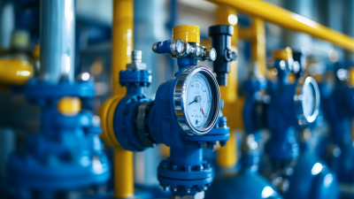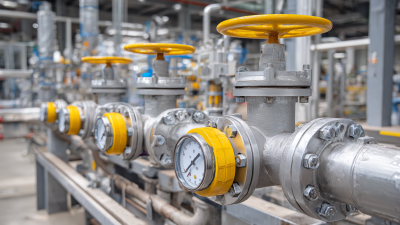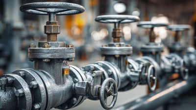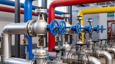
Automated Valves are changing how modern plants move, stop, and regulate fluids. They combine a valve body with an actuator, positioner, sensors, and a control signal. The result is a responsive device that can operate without constant manual adjustment.
In practical terms, a controller sends an electrical, pneumatic, or digital command. The actuator converts that command into movement. A ball valve may rotate 90 degrees. A globe valve may lift its stem several millimeters. The positioner checks the valve’s actual position and corrects errors. Small changes matter. A slight opening can influence pressure, temperature, flow rate, and production quality.
Greg McMillan, a respected process-control engineer, has described the control valve as “the most important final control element in a process control loop.” His observation explains why valve selection deserves careful attention. Engineers must match the valve to fluid properties, pressure, temperature, response speed, and failure requirements.
The hardware is not magical. It can stick, leak, respond slowly, or fail in an unsafe position. That reality is sometimes overlooked. A reliable system needs correct sizing, clean air supply, suitable materials, and regular inspection. Operators also need clear feedback from the control system.
This guide examines what Automated Valves are, how their components work, and where they fit in industrial systems. It also considers practical weaknesses. Automation improves consistency, but it does not remove the need for engineering judgment.
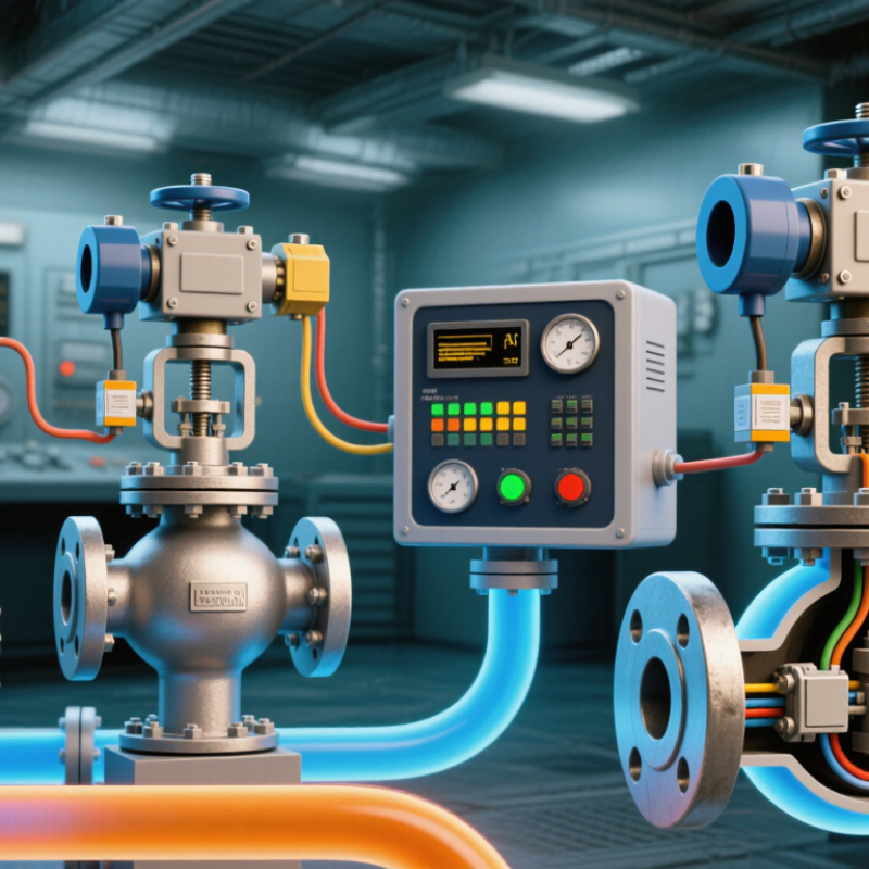
Automated valves are devices that control liquid or gas flow with limited manual effort. They combine a valve body with an actuator, controller, and sometimes sensors. The valve body opens, closes, or restricts the passage. The actuator supplies movement. The controller decides when movement should occur.
An electric actuator uses a motor and gears. A pneumatic actuator uses compressed air. Hydraulic systems use pressurized fluid for demanding applications. During operation, a sensor may measure pressure, temperature, level, or flow. The controller compares that reading with a programmed setting. It then signals the actuator to adjust the valve. The valve moves. For example, a tank sensor can detect a rising liquid level and trigger the inlet valve to close.
Automated valves can improve repeatability and reduce exposure to hot, corrosive, or high-pressure process lines. However, automation is not maintenance-free. Dust, moisture, incorrect wiring, and worn seals can cause slow or incomplete movement. That assumption fails. A valve may receive a signal yet remain partly closed. Technicians should verify actuator travel, connection integrity, fail-safe behavior, and actual flow conditions. They also need to confirm that the valve material matches the handled fluid. In field work, small calibration errors can create large process changes. Clear maintenance records help reveal these patterns before equipment performance becomes unreliable.
| Data Dimension | Description | How It Works | Typical Uses |
|---|---|---|---|
| Definition | An automated valve is a valve that opens, closes, or adjusts fluid flow without requiring continuous manual operation. | An actuator receives a control signal and converts energy into mechanical movement of the valve. | Industrial process control, water systems, heating and cooling, compressed air, and fluid-transfer systems. |
| Core Components | Valve body, closure element, stem or shaft, actuator, control signal interface, and required mounting hardware. | The actuator moves the stem, ball, disc, plug, or diaphragm to regulate the passage through the valve. | On/off isolation, throttling, pressure control, temperature control, and flow-rate management. |
| Electric Actuation | Uses an electric motor or electromagnetic mechanism to operate the valve. | An electrical command drives the actuator directly or through gearing. Position feedback may confirm the valve state. | Water treatment, HVAC systems, process equipment, and applications where precise positioning is required. |
| Pneumatic Actuation | Uses compressed air to generate linear or rotary movement. | Air pressure moves a piston or diaphragm. A spring may return the valve to a defined position when air pressure is removed. | Fast-cycling process lines, manufacturing equipment, chemical processing, and hazardous areas with suitable controls. |
| Hydraulic Actuation | Uses pressurized liquid to produce high mechanical force. | Hydraulic pressure acts on a piston or cylinder to rotate or move the valve closure element. | Large valves, high-pressure systems, power generation, and applications requiring substantial operating force. |
| Valve Movement | Automated valves may use linear or rotary motion. | Linear valves move a stem or plug along an axis; rotary valves turn a ball, disc, or plug around an axis. | Linear motion is common in globe and diaphragm valves; rotary motion is common in ball, butterfly, and plug valves. |
| Control Signals | Signals may be discrete or continuous, depending on the required control function. | A discrete signal commands open or closed operation, while a continuous signal sets an intermediate valve position. | Programmable controllers, process-control systems, building-management systems, and remote monitoring equipment. |
| On/Off Operation | The valve is intended to operate primarily in fully open or fully closed positions. | A command energizes or pressurizes the actuator until a limit switch, position sensor, or internal stop confirms the target position. | Isolation, tank filling, drainage, safety shutdown, and batch-processing sequences. |
| Modulating Operation | The valve continuously adjusts its opening to control flow or another process variable. | A controller compares the measured process condition with the desired setpoint and changes the actuator position accordingly. | Flow regulation, pressure control, level control, and temperature control. |
| Fail-Safe Position | A predetermined valve position used when power, air, hydraulic pressure, or the control signal is lost. | Spring-return actuators or backup systems move the valve to fail-open, fail-closed, or fail-in-place, depending on the process risk. | Emergency shutdown, burner protection, cooling systems, chemical isolation, and other safety-related processes. |
| Feedback and Monitoring | Sensors and switches provide information about valve position or actuator condition. | The control system uses feedback to verify movement, identify faults, and improve positioning accuracy. | Remote diagnostics, preventive maintenance, alarm systems, and automated process verification. |
| Main Benefits | Automated valves can improve repeatability, response time, operator safety, and process consistency. | Control signals allow valves to operate remotely or as part of an automatic sequence. | Reduced manual intervention, more consistent flow control, faster emergency response, and easier system integration. |
| Key Selection Factors | Selection depends on the fluid, pressure, temperature, flow requirements, valve size, cycle frequency, and required safety function. | The valve and actuator must be matched so the available torque or thrust is sufficient under operating and shutoff conditions. | Reliable operation in water, air, steam, gases, chemicals, slurries, and other process media when materials are properly specified. |
What Are Automated Valves and How Do They Work?
Key Components of an Automated Valve
An automated valve combines a valve body, an actuator, and a control signal. The valve body directs liquid, gas, or steam through a pipeline. Inside, a ball, disc, plug, or gate moves against the flow. The actuator supplies movement. Electric, pneumatic, and hydraulic actuators are common choices.
A controller sends instructions based on process conditions. A positioner compares the requested position with the valve’s actual position. It then corrects small errors. Sensors may monitor pressure, temperature, flow, or valve travel. These details matter near a pump, where sudden closure can create damaging pressure surges. Power supplies and signal cables also need protection from moisture and vibration.
Safety features deserve close attention. A spring-return actuator can move the valve to a safer position after power loss. Manual overrides allow technicians to operate the valve during testing or maintenance. In field inspections, loose wiring and incorrect actuator sizing appear more often than expected. A valve may look correctly installed but still respond slowly. That delay can disrupt an entire process. I have also found that control signals are not always the real problem; sticky internal parts can imitate electrical faults. Good commissioning checks movement, feedback, leakage, and response time under realistic conditions. Small oversights remain possible, especially when drawings differ from the installed piping.
Ideal relationship between a standard 4–20 mA control signal and automated valve position
An automated valve combines a valve body, actuator, control signal, and feedback or position-sensing components. In a typical calibrated system, a 4 mA signal represents 0% commanded opening and a 20 mA signal represents 100%. The controller sends the signal, the positioner interprets it, and the actuator moves the valve to regulate fluid flow.
What Are Automated Valves and How Do They Work?
How Automated Valves Operate Step by Step
An automated valve controls fluid or gas flow without constant manual turning. It combines a valve body, an actuator, and a control signal. The valve body contains the passageway and closing element. The actuator supplies movement through air pressure, electricity, or hydraulic power.
The process begins when a controller sends an opening, closing, or positioning command. A pneumatic actuator moves a diaphragm or piston. An electric actuator rotates a motor and gearbox. This motion turns the valve stem or shifts its internal element. The valve then changes the flow rate. Small movements can produce significant pressure changes.
Sensors may report position, pressure, temperature, or flow. A positioner compares the requested position with the actual position. It corrects movement when the valve stops too early or moves too far. Not every installation needs the same feedback equipment. That choice depends on process risk, accuracy, and operating conditions.
During commissioning, technicians check wiring, air pressure, travel limits, and emergency settings. A fail-open or fail-closed action must match the process hazard. Dirt, moisture, and incorrect sizing can cause slow responses or leakage. This step is often underestimated. A valve may appear functional while performing poorly under real pressure. Regular inspection helps reveal worn seals, loose connections, and inaccurate feedback before they disrupt control.
Automated valves control fluid or gas flow without constant manual operation. An actuator receives a signal from a controller, then opens, closes, or adjusts the valve. Electric actuators suit accurate positioning and clean indoor systems. Pneumatic actuators respond quickly and work well in hazardous process areas. Hydraulic actuators deliver strong movement for large, high-pressure lines.
Valve type should match the application. Ball valves provide tight shutoff in water, air, and chemical lines. Butterfly valves are lighter and economical for large pipes, such as cooling-water systems. Globe valves offer precise throttling in steam and process control. Gate valves suit fully open or fully closed service, but they are poor choices for frequent adjustment. Diaphragm valves protect sensitive fluids from contamination. Check valves prevent reverse flow, although they are not usually used for active control. In wastewater plants, automated valves manage filtration and dosing stages. In heating systems, they regulate hot-water circulation. Food processing requires hygienic designs and careful cleaning access.
Tips: Confirm pressure, temperature, pipe size, and fluid compatibility before selection. Check the actuator’s fail position during power or air loss. A safe failure mode matters. Leave room for maintenance around the valve. Field technicians often find that poor sizing causes unstable flow and early wear. No valve choice is perfect. Engineers should review real operating conditions, not only catalog ratings. A small pressure drop can become important across a busy production line.
Automated valves combine a valve body, actuator, controller, and position feedback. A control signal moves the actuator, which opens, throttles, or closes the valve. Feedback confirms the actual position. In practical use, this reduces manual intervention and supports repeatable flow control. A 2024 MarketsandMarkets report estimates the automated valve market will grow steadily through 2029, driven by process automation and stricter efficiency targets. The estimate is useful, but it is not a site performance guarantee.
The benefits are measurable. Automated valves can improve response time, reduce operator exposure, and regulate pressure more consistently. They also support remote monitoring in water, energy, and chemical facilities. Yet automation adds failure points. Loss of air, power, communication, or calibration can leave a valve in the wrong position. Incorrect sizing may cause hunting, noise, cavitation, or slow movement. More equipment does not always mean better control. That is an uncomfortable lesson.
Maintenance should include stroke testing, actuator inspection, position verification, and leak checks. Inspectors should examine seals, tubing, wiring, and mounting hardware. ISA-75 standards provide recognized guidance for control-valve performance and testing. A 2023 U.S. Department of Energy report also highlights that compressed-air leaks can waste substantial energy, making pneumatic systems worth auditing regularly. Maintenance intervals depend on cycle frequency, media, temperature, and vibration. Quarterly checks may suit a clean utility line, but harsh service can demand weekly attention. Records matter. Without them, a “healthy” valve may only be an assumption.