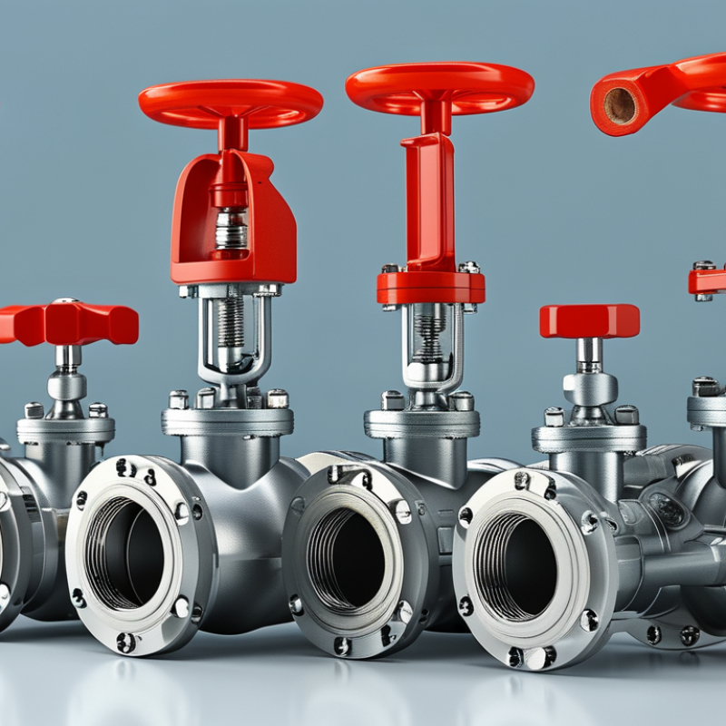
Choosing the right Ball Valve Control Valve begins with understanding the process, not simply comparing product prices. The medium, pressure, temperature, flow rate, and pipe size all influence the final selection. A valve handling clean water may perform well with standard seals. The same design could fail quickly with abrasive slurry or corrosive chemicals. Small details matter.
Experienced engineers usually review operating conditions before choosing an actuator or control signal. They check whether the valve needs on-off control, throttling, or emergency shutoff performance. A stainless steel body may suit demanding environments, while a resilient-seated design can provide reliable isolation in less severe systems. Actuator torque must also account for pressure differences, friction, and possible scale buildup. Undersizing creates unstable control. Oversizing can reduce accuracy.
Inspection records, manufacturer data, and recognized testing procedures provide stronger evidence than attractive catalog language. Confirm material compatibility, leakage ratings, connection standards, maintenance access, and spare-part availability. A practical trial under realistic conditions can reveal problems that calculations miss. No selection method is perfect. Real systems change, and assumptions sometimes prove wrong. That is why experienced teams document their reasoning and reassess the valve after installation. This guide explains the main selection factors clearly, helping maintenance managers, engineers, and buyers choose a Ball Valve Control Valve with greater confidence, safer operation, and more predictable long-term performance.
A ball valve control valve regulates fluid flow by rotating a drilled ball inside its body. A quarter-turn actuator can move from open to closed quickly. This design suits water, air, gas, and many industrial liquids. However, fast movement does not always mean accurate control. The valve must match the process requirements.
During selection, check the medium, pressure, temperature, pipe size, and required flow range. A smaller valve may control low flow more accurately than an oversized valve. An oversized valve often stays nearly closed, causing unstable movement and poor response. The flow coefficient, or Cv, helps engineers match valve capacity with actual demand. For abrasive or corrosive media, material compatibility matters greatly.
The actuator also affects performance. Electric actuators support precise positioning, while pneumatic actuators can respond quickly during process changes. Specify the correct fail-open or fail-closed position for safe operation. In practical commissioning, technicians should inspect signal response, stem movement, leakage, and unusual vibration. Cavitation may sound like gravel inside the pipeline. That warning should not be ignored. I have found that calculations alone can miss real operating problems, especially when flow conditions change. Test the valve under realistic pressure whenever possible. A technically correct selection can still perform poorly if installation, calibration, or maintenance is overlooked.
Ball valves are typically selected for fast quarter-turn operation, reliable shutoff, and low pressure loss. They are especially suitable for isolation, on/off process control, and emergency shutdown service. For precise continuous throttling, a purpose-designed control valve may provide better performance.
Rating scale: 1 = limited suitability, 5 = strong suitability. The ratings represent typical engineering characteristics of ball valve control valves and can vary with valve design, actuator type, trim, pressure class, and process conditions.
Choosing the Right Ball Valve Control Valve
A reliable selection begins with the process, not the valve catalog. Define the fluid, normal flow, minimum flow, maximum flow, pressure, and temperature. Record upset conditions too. They often expose weak choices.
For liquid service, calculate the required flow coefficient at several operating points. A valve sized only for maximum flow may operate nearly closed during normal production. That can reduce control accuracy and increase wear. For gases, consider pressure ratio, density, sonic flow, and noise limits. Watch for cavitation and flashing in high-pressure liquid services. The valve body, trim, and seals must match the fluid’s chemistry and temperature. Compatibility charts help, but field conditions can be less tidy than laboratory data.
Operating action also matters. Choose pneumatic, electric, or hydraulic actuation according to available utilities, response time, and maintenance access. Specify the required fail position after air, power, or signal loss. Check shutoff requirements, cycling frequency, actuator torque, and control signal range. A ball valve can deliver strong shutoff, but it may not provide stable throttling when poorly sized. That mistake is common.
Leave room for review. Process data may be incomplete or based on averages. Confirm actual line size, upstream disturbances, pipe supports, and installation orientation before approval. A short site inspection can prevent a costly redesign. Safety requirements, pressure ratings, and applicable codes should be verified by qualified personnel.
| Selection Dimension | Process Information to Confirm | Typical Design Guidance | Recommended Ball Valve Configuration | Key Selection Notes |
|---|---|---|---|---|
| Fluid Type | Liquid, gas, vapor, slurry, corrosive chemical, hydrocarbon, water, or utility service. | Identify chemical compatibility, toxicity, flammability, cleanliness, and solids content before selecting materials. | Use a full-port or reduced-port valve with body, ball, stem, and seat materials compatible with the fluid. | Material compatibility must cover the process fluid, additives, cleaning chemicals, and expected contaminants. |
| Operating Temperature | Normal, minimum, maximum, startup, shutdown, cleaning, and upset temperatures. | Check the complete temperature rating of the valve assembly, including seats, seals, packing, actuator, and accessories. | Soft seats are commonly used for moderate temperatures; metal-seated designs are considered for high temperature or severe service. | Do not select the valve from body temperature rating alone; seat and seal limits can be lower. |
| Operating Pressure | Normal pressure, maximum allowable working pressure, differential pressure, pressure surges, and vacuum conditions. | Choose a pressure class or rating that exceeds the maximum design pressure at the actual operating temperature. | Floating ball valves are often suitable for lower to moderate pressure duties; trunnion-mounted designs are commonly used for larger sizes or higher differential pressure. | Account for blocked-in thermal expansion, pump shutoff pressure, water hammer, and relief-system settings. |
| Valve Size | Required flow rate, line size, allowable pressure drop, velocity limits, and available installation space. | Size the valve for the required flow rather than automatically matching the pipe diameter. | Use full-port construction when low pressure loss, pigging, or high flow capacity is important; reduced-port construction may be suitable where lower cost or better control range is acceptable. | Oversizing can reduce controllability and cause operation near the closed position; undersizing can create excessive pressure loss and noise. |
| Flow Capacity | Liquid flow rate, gas or vapor mass flow, inlet and outlet pressure, density, viscosity, and required flow coefficient. | Calculate the required flow coefficient using the applicable liquid or gas sizing method and verify the valve's usable operating range. | For control duty, select a characterized ball design or V-port configuration when a more predictable relationship between travel and flow is required. | Use actual operating conditions, not only nominal pipe size, when calculating capacity. |
| Control Function | On/off isolation, throttling, modulating control, emergency shutdown, or fail-safe operation. | Ball valves are naturally suited to tight shutoff and quarter-turn isolation; continuous throttling requires a design intended for control service. | Use a standard full-bore ball valve for isolation; use a characterized or V-port ball valve for modulating service. | Frequent throttling with a standard full-port ball valve can produce poor resolution, seat wear, noise, and erosion. |
| Shutoff Requirement | Required leakage class, allowable leakage, double isolation needs, and pressure direction. | Specify the applicable shutoff or leakage standard and define whether tight shutoff is required in one or both flow directions. | Soft-seated valves generally provide very low leakage at moderate temperature; metal-seated valves are selected where temperature, abrasion, or fire exposure limits soft seats. | Confirm whether the valve must provide bidirectional shutoff and whether cavity relief or double-block-and-bleed capability is required. |
| Fluid Cleanliness and Solids | Particle size, concentration, abrasiveness, crystallization, polymerization, and risk of deposits. | Evaluate erosion, seat damage, cavity buildup, and the possibility of the ball sticking during long periods of inactivity. | Consider a metal-seated, abrasion-resistant, or specialized cavity design for abrasive or solids-containing service. | Soft seats are vulnerable to scratching and may not be suitable for abrasive slurries or contaminated streams. |
| Actuation Method | Required torque, operating frequency, available power, response time, and manual override needs. | Determine breakaway, running, and end-of-travel torque under the worst pressure, temperature, and seating conditions. | Pneumatic actuators are common for fast quarter-turn operation; electric actuators suit locations with electrical power and controlled positioning; manual gear operators suit infrequent operation. | Include an engineering safety factor and account for increased torque caused by seat friction, contamination, or low-temperature service. |
| Failure Position | Safe state during loss of air, electricity, signal, or control-system communication. | Define whether the valve must fail open, fail closed, or fail in place based on the process hazard analysis. | Use spring-return actuation for fail-open or fail-closed operation; use double-acting actuation only where the process assessment permits loss of stored energy without automatic movement. | The correct failure position depends on the process consequence, not on the valve type alone. |
| Control Signal and Positioning | Input signal, control-loop requirements, desired accuracy, cycle frequency, and feedback needs. | Match the actuator and positioner to the control signal, response time, environmental rating, and required travel resolution. | Use a positioner for modulating applications and position feedback for monitoring, interlocks, or automated sequencing. | Verify compatibility with the control system and ensure that the actuator can achieve the required full operating cycle. |
| Cavitation and Noise | Liquid pressure drop, vapor pressure, gas velocity, compressibility, and expected sound limits. | Evaluate cavitation for liquids and choked flow or excessive aerodynamic noise for gases and vapors. | Use an appropriate characterized trim, staged pressure reduction, or a different control-valve design when the pressure drop is severe. | A ball valve may not be the best choice for extreme continuous pressure reduction or severe cavitation service. |
| Materials and Corrosion | Chlorides, acids, caustics, sour components, oxygen, seawater, external atmosphere, and galvanic-coupling risks. | Select wetted materials and surface treatments using verified corrosion data for the actual concentration and temperature. | Specify suitable body alloys, trim materials, coatings, seat compounds, and packing based on the service environment. | Corrosion resistance can change significantly with concentration, temperature, velocity, and the presence of water or oxygen. |
| Emissions and Safety | Hazardous area classification, fugitive-emission limits, fire exposure, static electricity, and toxic-fluid containment. | Specify fire-safe construction, antistatic provisions, suitable stem sealing, and emissions performance where required by the installation. | Use a fire-tested and low-emission configuration when required by the process safety specification. | Confirm applicable local codes, hazardous-area requirements, and testing standards before purchase. |
| Installation Conditions | Pipe orientation, access, ambient temperature, vibration, outdoor exposure, drainage, and maintenance clearance. | Provide adequate support, actuator clearance, safe access, and protection from unacceptable external loads. | Use an orientation and actuator arrangement that permits inspection, manual override, calibration, and removal without unsafe access. | Check flange, end-connection, face-to-face, pressure-class, and piping-material compatibility. |
| Operating Frequency and Service Life | Expected cycles per hour or day, continuous modulation, idle periods, and required service interval. | Compare the expected duty cycle with the rated mechanical and actuator life. | Choose robust stem, seat, bearing, and actuator arrangements for high-cycle or continuous-control applications. | Frequent cycling, abrasive media, and high differential pressure can significantly shorten seat and actuator life. |
| Maintenance Requirements | Availability of spare parts, isolation capability, inspection intervals, cleaning method, and plant maintenance practices. | Prefer standardized, maintainable construction with accessible seals and documented torque and test requirements. | Consider replaceable seats and seals, drain or vent connections, position indication, and lockout provisions where appropriate. | Plan for isolation, depressurization, draining, and verification of zero energy before maintenance. |
| Final Verification | Process datasheet, piping specifications, safety requirements, control philosophy, and applicable standards. | Review the complete valve, actuator, accessories, materials, ratings, sizing calculations, and test documentation as one assembly. | Approve the selection only after confirming that the valve meets process, mechanical, control, safety, and maintenance requirements. | The best selection is the one that satisfies the complete operating envelope, not just the nominal pressure and pipe size. |

Choosing the right ball valve control valve starts with the process medium. Stainless steel suits many corrosive fluids, while carbon steel is often practical for dry, non-corrosive service. Plastic bodies can reduce cost, but temperature limits arrive quickly. I have seen a valve fail because the fluid was “mostly clean.” Mostly is not an engineering specification.
Size the valve for controlled flow, not simply for matching pipe diameter. Oversized valves often operate nearly closed, causing unstable regulation and unnecessary wear. The International Society of Automation’s control-valve guidance recommends checking flow coefficient, pressure drop, and cavitation risk together. A 2-inch pipe may still require a smaller trim. That detail matters.
Pressure ratings require careful reading. A Class 150 valve does not always withstand 150 psi at every temperature. ASME B16.34 pressure-temperature tables can reduce allowable pressure as temperature increases. End connections also affect installation reliability. Flanged ends simplify removal, threaded ends suit smaller lines, and welded ends reduce leak paths in permanent systems. The 2022 U.S. Department of Energy steam-system guidance identifies leakage, poor pressure control, and weak maintenance as recurring efficiency losses. API 598 testing requirements should be reviewed before acceptance, especially for shell and seat leakage. I still recheck actuator torque after selecting the valve; friction, differential pressure, and cycling frequency can change the result.
Choosing the right ball valve control valve starts with the actuator. Match its torque to the valve’s breakaway torque, operating pressure, temperature, and media. Add a practical safety margin, but avoid excessive sizing. An oversized actuator can increase cost and reduce control sensitivity.
Pneumatic actuators suit fast, repetitive operation where compressed air is available. Electric actuators fit installations needing simple wiring, accurate positioning, or quieter movement. The control method also matters. On-off service needs reliable end-position signals. Modulating service requires a suitable positioner and a stable control signal, such as 4–20 mA. Slow response can create pressure swings.
Safety features deserve careful attention. Select fail-open, fail-closed, or fail-in-place action according to the process hazard. Spring-return actuators can move the valve during power or air loss. Include local manual override only when operators can use it safely. Confirm limit switches, position feedback, enclosure protection, and emergency shutdown compatibility. Test these features under realistic conditions.
A common mistake is choosing from valve size alone. Differential pressure often changes the real torque demand. Temperature can also affect seals and actuator performance. Review the valve data sheet, control diagram, and failure assessment together. Field conditions are rarely perfect. That assumption needs checking. Record the selected torque, signal type, response time, and fail position before purchase.
Selecting the right ball control valve starts with installation, not catalog price. Confirm medium, pressure, temperature, flow range, and actuator torque. A valve placed in a cramped rack becomes a maintenance problem. Leave clearance for bolt removal, position indicators, and actuator access. Keep the stem orientation practical. Follow applicable piping and control standards, including IEC 60534 guidance for control-valve sizing. Oversizing is common. It can create unstable low-opening operation and poor process control.
Maintenance cost depends on isolation, inspection, and replacement time. Specify block-and-bleed arrangements where process risk requires them. Verify that seats and seals suit the fluid. The U.S. Department of Energy’s Operations & Maintenance Best Practices Guide reports potential energy savings of 5–20% from effective O&M programs. That figure is not a valve guarantee, but it shows why accessible maintenance matters. Check torque trends, leakage, cycle counts, and actuator response. Shorter inspections help.
For lifecycle cost, compare purchase price, installation labor, spare parts, calibration, downtime, and disposal. NIST Handbook 135 treats acquisition as only one part of life-cycle costing. Use documented failure data, not hopeful assumptions. API 608 requirements can support robust ball-valve selection, but compliance alone does not prove long-term reliability. A cheaper body may win approval today. It may lose after one difficult shutdown. Review the decision with operators and maintenance technicians; they often notice access problems that drawings hide.